 贴图轴
贴图轴
|
Toolbar |
Menu |
Shortcut |
|---|---|---|
|
|
Edit Object Properties Window Panels > Properties |
F3 |
贴图轴属性管理被选曲面、多重曲面和网格的贴图轴投影的设定。
贴图轴可以用不同的方式将 2D 贴图投影到 3D 模型上。
贴图可应用于三维模型的曲面,为其添加颜色、贴图或其它曲面细节(光泽度、反射率或透明度)。
2D 贴图以 UV 坐标对应到 3D 模型上,UV 坐标的 u 代表贴图的横向量(左到右),v 代表贴图纵向量(上到下)。
任何时候将图像应用到材质中,然后将该材质应用到模型中,都会用到 uv 贴图轴。
贴图轴通道
一个贴图通道包含一组贴图参数,贴图轴通道通过其数字序号来区别,一个物件可以有多个贴图轴通道,每个贴图轴通道可以使用不同的贴图轴类型。
材质里的各种型式的贴图可以设定不同的通道,贴图是以通道编号相同的贴图轴对应至物件上。贴图的通道预设为 1。
如果一个物件未被赋予贴图轴,则曲面贴图轴将贴图对应至物件上。
![]() 属性面板
属性面板
在材质贴图中设置的环境贴图、屏幕和 WCS* 贴图轴样式会覆盖贴图轴属性。
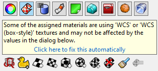
单击消息下方的蓝色文本字符串,将材质贴图更改为使用。
 拆解 UV
拆解 UV
展开贴图以进行编辑。
参考: Unwrap。
 自定义贴图轴
新增一个自定义贴图轴通道。
 曲面贴图轴
曲面贴图轴
新增一个曲面贴图轴通道,曲面和多重曲面的默认贴图轴映射方法是由曲面的控制点结构决定的。
 平面贴图轴
平面贴图轴
新增一个平面贴图轴通道。
 立方体贴图轴
新增一个立方体贴图轴通道。
 球体贴图轴
球体贴图轴
新增一个球体贴图轴通道。
 圆柱体贴图轴
新增一个圆柱体贴图轴通道。
 Apply OCS Mapping
Line up textures with the object rather than the world coordinates. Details...
 删除贴图轴
删除贴图轴
删除贴图轴通道。
 匹配贴图轴
匹配贴图轴
将贴图轴匹配到另一个物件的贴图轴。
 编辑通道 (仅适用于“使用多个贴图轴通道”选项启用时)
允许更改贴图轴使用的通道编号。
 显示贴图轴
显示贴图轴
显示物件的贴图轴小部件。
 隐藏贴图轴
隐藏贴图轴
隐藏所有物件的贴图轴小部件。
 Select Mapping Widgets
Select all texture mapping widgets of the selected object.
Use Show Mapping first.
 UVEditor
打开 UV 编辑器。
参考: UV编辑器。
使用多个贴图轴通道
允许一个物件有多个贴图轴通道。可以使用编辑通道图标更改通道的编号。这些贴图轴通道编号用于物件材质的贴图设置,以管理每个贴图应该使用哪个贴图轴通道。
名称
贴图轴名称。
See: Naming conventions in Rhino
投影
最接近点
射线
类型
贴图轴类型。
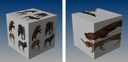
曲面
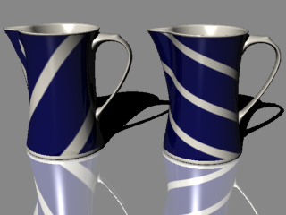
曲面贴图轴会在物件上拉伸贴图。
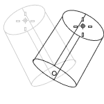
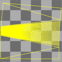
以这个不等距圆角的多重曲面为例,因为每个曲面都有自己的 UV 坐标,所以使用曲面贴图轴时三个曲面上的贴图无法连续。
参考: ApplySurfaceMapping。
平面
平面贴图轴可以将一个二维平面投影到物件的上。
参考: ApplyPlanarMapping。
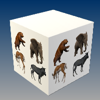
立方体
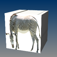
立方体贴图轴可以将一个三维立方体投影到物件上。
参考: ApplyBoxMapping。
立方体 (未加盖)
此贴图轴仅适用于立方体的侧面,不会投影到顶部和底部曲面。
参考: ApplyBoxMapping。
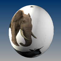
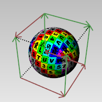
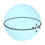
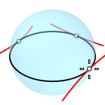
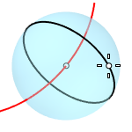
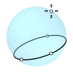
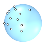
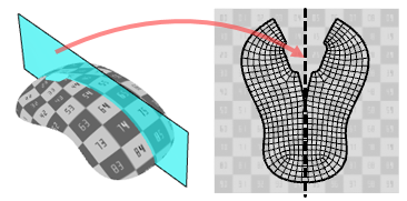
球体
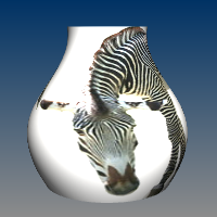
球体贴图轴将物件包裹在球体周围,贴图的顶部边缘收缩为顶部极点,底部边缘收缩为底部极点。
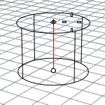
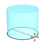
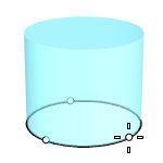
圆柱体
圆柱体贴图轴将贴图卷成圆柱状再包裹至物件上。
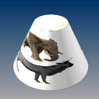
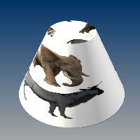
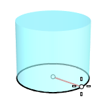
加盖圆柱体
加盖圆柱体贴图轴还会将图像投影到圆柱的顶部和底部。
OCS 框
当使用 WCS/OCS 或 WCS/OCS (立方体类型) 贴图轴时,OCS 框类型将贴图与物件对齐,而不是与世界坐标对齐。此贴图轴类型只能通过 ApplyOcsMapping 指令添加。
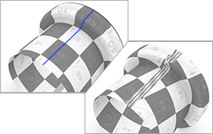
自定义
新增一个自定义贴图轴通道。
自定义物件控制贴图轴在其它物件上的映射方式。
此过程仅限于单一曲面,因为要通过曲面控制点的结构控制映射。此处,当指令行提示输入自定义物件时,选择多重曲面前的曲面。
自定义贴图轴操作步骤
- 选取自定义贴图轴物件。
投影
当网格被赋予贴图轴时,必须将另一个物件的一些 UV(W) 值分配给每个顶点 –要么是一个球体,要么是一个自定义物件(另一个网格或曲面)。
每个网格顶点都从另一个物件的 UV 空间分配一个参数。
最接近点
以最接近点将 UV 坐标映射至网格顶点。
射线
以法线方向将 UV 坐标映射至网格顶点。
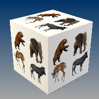
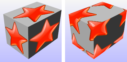
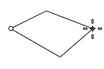
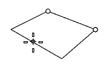
贴图分布
单一贴图分布(左),分段贴图分布(右)。
单一
指定贴图在每个独立空间上单独映射。
分段
指定每个空间使用贴图的不同区域,六个独立的贴图空间分别匹配图像的不同部分。
XYZ 位置
在世界坐标中设置贴图轴小部件的中心点的位置。
-
Right-click on the slider to set min/max value, incremental precision and decimal places for the value. They are used when you double-click on the slider to enter the value or use the up or down key to change the value.

默认位置(左),移动到另一个位置(右)。
 指定按钮
指定按钮
单击以在屏幕上指定一个位置。
XYZ 旋转
设置贴图在世界空间中的旋转。
-
Right-click on the dial indicator to set incremental precision and decimal places for the angle value. They are used when you double-click on the dial indicator to enter the value or use the up or down key to change the value.
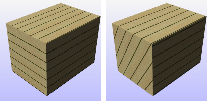
默认旋转 (左), x 轴旋转 60 度 (右)。
XYZ 大小
贴图轴大小。
 所有方向的大小都设置为 1
将三个方向的贴图大小设置为1。
 所有方向的大小设置相同
将三个方向的贴图大小设置为相同大小。
 通过原始贴图轴适配物件
根据原始贴图轴将贴图适配到物件上。
 将大小设置为图像的长宽比
将尺寸设置为图像的长宽比。
 Lock Size
当贴图轴小部件以不均等缩放方式调整大小时,缩放锁定为指定的宽高比。
UVW 偏移
贴图从 UVW 贴图空间的原点偏移的量。
UVW 拼贴
贴图在 UVW 贴图空间中的物件上重复的次数。
锁定
当勾选锁定时,u、v和w的拼贴值可以一起更改。三个数值会保持之前的特定关系同步增长或减少。
当取消勾选锁定时,可以独立更改拼贴数值。
范例:
如果锁定是关闭的,当您在 UVW 方框中分别输入1、2、3时,贴图会在 u 方向重复一次,v 方向重复两次,w 方向重复三次。
如果您之后勾选锁定,并将1更改为2,则数值将同步更新为2、4、6。如果您随后将6更改为60,则数值又更新为20、40、60.
UVW 旋转
贴图在 UVW 贴图空间中的物件上的旋转角度。
相关指令
| Toolbar | Menu |
|---|---|
|
|
|

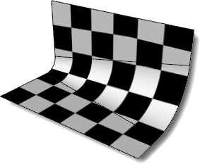
ApplyBoxMapping 指令可以为物件添加一个立方体贴图轴通道,并将贴图轴类型设为立方体。
立方体贴图轴打开的物件。
步骤
-
建立立方体贴图轴。
-
选择坐标系统。
-
指定立方体贴图轴是否加盖。
-
Enter a mapping channel number, or press Enter to accept the default value.
指令行选项
BoundingBox
Uses the object bounding box to determine the location and size of the mapping widget.
CPlane
Uses Construction plane coordinates for the bounding box.
World
Uses World coordinates for the bounding box.
Diagonal
Creates a box from the diagonal corners. If you pick the two corners on the CPlane, the command prompts for picking the height.
(Default)
Draws the rectangle using two opposite corners.
3Point
Draws the rectangle using two adjacent corner locations and a location on the opposite side.
EdgeMidpoint
Draws the rectangle from the midpoint of the first edge, an end of the edge, and a location on the opposite side.
Vertical
Draws the rectangle perpendicular to the construction plane.
Center
Draws the rectangle from the center point and a corner.
加盖
建立有上、下盖的立方体贴图轴。
| Toolbar | Menu |
|---|---|
|
|
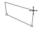
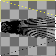
ApplyCylindricalMapping 指令可以向物件添加贴图轴通道,并将贴图轴类型设为圆柱体。
曲面贴图轴 (左) 与圆柱体贴图轴 (右)。
步骤
建立圆柱体贴图轴。
选择坐标系统。
指定圆柱体贴图轴是否加盖。
Enter a mapping channel number, or press Enter to accept the default value.
指令行选项
BoundingBox
Uses the object bounding box to determine the location and size of the mapping widget.
CPlane
Uses Construction plane coordinates for the bounding box.
World
Uses World coordinates for the bounding box.
DirectionConstraint
Direction constraints restrict the direction of the cylinder.
None
Pick or type a number to set the height.
- Use elevator mode, object snaps, or other modeling aids to help picking a location.
- The cursor location defines the positive direction when you type a number to set the height.
Vertical
Creates a cylinder perpendicular to the construction plane.
- The CPlane +Z direction defines the positive direction when you type a number to set the height.
AroundCurve
Draws the base circle perpendicular to the picked point on a curve. The center line of the cylinder will be tangent to the curve.
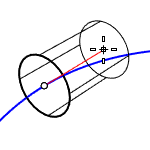
- The curve direction defines the positive direction when you type a number to set the height.
Radius
Draws the base circle by picking the center point and a radius point.
2Point
Draws the base circle from two opposite points.
3Point
Draws the base circle through three points.
Tangent
Draws the base circle tangent to one, two, or three curves.
FitPoints
Draws the base circle by fitting to selected points, control points, or mesh vertices.
加盖
建立有上、下盖的圆柱体贴图轴。
| Toolbar | Menu |
|---|---|
|
|
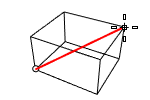
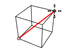
ApplyCustomMapping 指令赋予物件自定义的贴图轴。
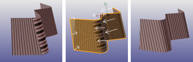
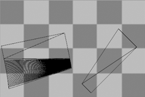
没有贴图轴 (左)、赋予其它物件的贴图轴 (中)、结果 (右)。
以一个网格、NURBS 曲面或多重曲面建立另一个物件的贴图轴,建立的贴图轴与用来建立贴图轴的物件之间没有连结,所以删除该物件并不影响已建立的贴图轴。
步骤
- 选取目标物件。
- 选取用来建立自订贴图轴的曲面或网格。
- Enter a mapping channel number, or press Enter to accept the default value.
已经应用于物件的自定义贴图轴可以通过 ExtractCustomMappingObject 指令进行抽离。
Toolbar | Menu |
|---|---|
|
|
当使用 WCS/OCS 或 WCS/OCS (立方体类型) 贴图轴时,ApplyOcsMapping 指令可以将贴图与物件对齐,而不是与世界坐标对齐。
| Toolbar | Menu |
|---|---|
|
|
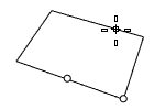
ApplyPlanarMapping 指令加入贴图轴通道至物件,并将贴图轴类型设为平面。
步骤
建立平面贴图轴。
选择 UV 可用于二维贴图轴,选择 UVW 可用于三维贴图轴。
Enter a mapping channel number, or press Enter to accept the default value.
指令行选项
BoundingBox
Uses the object bounding box to determine the location and size of the mapping widget.
CPlane
Uses Construction plane coordinates for the bounding box.
World
Uses World coordinates for the bounding box.
立方体
绘制一个立方体用于建立平面贴图轴。
(Default)
Draws the rectangle using two opposite corners.
3Point
Draws the rectangle using two adjacent corner locations and a location on the opposite side.
EdgeMidpoint
Draws the rectangle from the midpoint of the first edge, an end of the edge, and a location on the opposite side.
Vertical
Draws the rectangle perpendicular to the construction plane.
Center
Draws the rectangle from the center point and a corner.
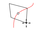
AroundCurve
Draws a rectangle perpendicular to a curve.
UV
U 和 V 坐标取自平面尺寸,W 坐标始终为零。
UVW
U 和 V 坐标取自平面尺寸,W 坐标取自法线到平面的距离。
| Toolbar | Menu |
|---|---|
|
|
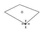
ApplySphericalMapping 指令加入贴图轴通道至物件,并将贴图轴类型设为球体。
步骤
- 选取物件,按 Enter 键。
- 建立球体贴图轴。
- Enter a mapping channel number, or press Enter to accept the default value.
指令行选项
BoundingBox
Uses the object bounding box to determine the location and size of the mapping widget.
CPlane
Uses Construction plane coordinates for the bounding box.
World
Uses World coordinates for the bounding box.
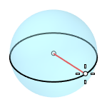
Radius
Creates a sphere by picking the center point and a radius point.
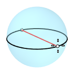
2Point
Creates a sphere from two opposite points on the base circle.
3Point
Creates a sphere from three points on the base circle.
Tangent
Creates a sphere with the base circle tangent to one, two or three curves.
AroundCurve
Creates a sphere from its center point on a curve, and a point on the base circle perpendicular to the curve.
4Point
Creates a sphere from three points on a section circle and a point on the sphere.
FitPoints
Creates a sphere by fitting to selected point objects, curve and surface control points, and mesh vertices.
| Toolbar | Menu |
|---|---|
|
|
ApplySphericalMapping 指令加入贴图轴通道至物件,并将贴图轴类型设为曲面。
| Toolbar | Menu |
|---|---|
|
|
The ExtractUVMesh command creates separate mesh objects extracted from the flattened UV space meshes of a model.
步骤
- 选取支持的物件类型。
- 指定所需的贴图轴通道。
- 绘制一个矩形。
指令行选项
1to1
Creates the mesh with the approximate area of the 3-D object.
The mesh can be used by a cutting machine for cutting shapes out of a material.
| Toolbar | Menu |
|---|---|
|
|
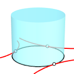
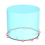
MappingWidget 指令可以打开所选物件的贴图轴小部件。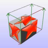
立方体贴图轴小部件:
- 以图形方式显示如何使用基础物件(立方体、圆柱体、球体或平面)将贴图映射绑定到物件上。
- 可以通过普通的 Rhino 指令拖动、移动、旋转和缩放。
- 可以打开它的控制点来调整它的大小。
指令行选项
显示OCS框
显示通过 ApplyOcsMapping 指令添加到物件的 OCS 框。
此选项仅在所选物件具有 OCS 框时可见。
| Toolbar | Menu |
|---|---|
|
|
MappingWidgetOff 指令可以关闭所选物件的贴图轴小部件。
| Toolbar | Menu |
|---|---|
|
|
MatchMapping 指令可以更改所选物件的贴图轴属性以复制指定物件。
您也可以在贴图轴属性面板中使用匹配贴图轴按钮。
| Toolbar | Menu |
|---|---|
|
|
RemoveMappingChannel 指令可以从物件中删除指定的贴图轴通道。
步骤
- 选取物件。
- 输入贴图轴通道序号。
| Toolbar | Menu |
|---|---|
|
|
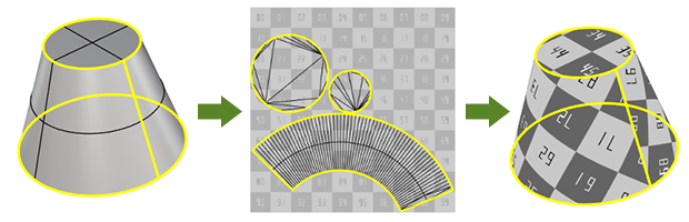
Unwrap 指令提示在被选择的物件上选择边缘作为贴图接缝,物件的渲染网格将在 UV 空间中被分割。
输入
- 曲面、多重曲面、挤出物件、网格、细分物件
步骤
执行指令。
选取一个或多个物件并按 键。
多个被选中的物件在 UV 空间中不会重叠。
Select a mapping channel.
选取物件的边缘。
使用指令行选项帮助选取边缘。
选取完毕后按下 键。
- 使用 UVEditor 指令在 UV 空间中编辑展平的渲染网格,以指定材质贴图的哪个部分将显示在物件上。
- Use the same steps to add/remove unwrap seams of an object.
指令行选项
连锁选取
连锁选取接缝。
套用
套用接缝选择。
编辑
打开 UV 编辑器。
取消
取消指令。
贴图轴通道
Selects a mapping channel number for the UV mesh.
仅未熔接(仅限网格)
只可选择未熔接的网格边缘。
对称提示
定义物件上的对称平面以对称展开物件。
请参考 Rectangle 指令的选项说明。
未熔接接缝(仅限网格)
沿着未熔接接缝拆解网格边缘,以避免接缝附近的贴图轴失真。实际的网格几何体将被修改。
方式
Conformal
Uses the Least Squares Conformal Map (LSCM) algorithm to flatten 3D objects.
AngleBased
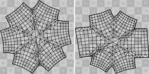
Uses the Angle Based Flattening (ABF++) algorithm to flatten 3D objects.
ABF (left) gives a more symmetric result than LSCM (right).
ABF requires even mesh tessellation to produce better results. Disable Simple planes and set Maximum aspect ratio smaller than 2 in the document render mesh settings to create the kind of render meshes.
AsRigidAsPossible
Uses the As-Rigid-As-Possible (ARAP) algorithm to flatten 3D objects. ARAP keeps texture size more even across the object than LSCM and ABF.
ShowEnds
Displays points on the open ends of selected unwrap seams.
请参考
| Toolbar | Menu |
|---|---|
|
|
UVEditor 指令可以编辑影响原始物件贴图坐标的网格,贴图网格可以组合和拆分,还可以编辑它们的控制点。
步骤
- 选取物件。
- Edit the UV mesh in the UVEditor window.
Scriptable command-line options
To access scriptable command-line options
- Type a hyphen in front of the command name: -UVEditor.
Mapping Channel
The UV mesh of the specified channel displays when UV Editor opens. More information...
拼合的曲面贴图轴坐标被投影到世界 xy 平面,分配给物件的贴图也显示在同一区域中。
The texture coordinates are represented as a collection of UV meshes.
When the UV meshes are edited, the texture changes on the object.
If an interior surface seam is selected in the polysurface when unwrapping, that seam will separate in the resulting flattened mapping meshes.
While the editor is open, vertices of the UV mesh can be turned on, and editing commands such as Scale1D, SetPt, and CageEdit can be used to adjust the UV mesh.
没有 UV 坐标的网格 (例如, 从 STL 文件导入)不需要编辑 UV 网格。在使用 UVEditor 指令之前,您需要展开网格或将贴图轴应用到网格。
UV Islands
A UV island is an independent part of a UV mesh.
From mapping channel
Select a mapping channel to display the associated UV mesh in the view.
 Hide unused UV islands
Hides the UV islands that do not have textures assigned.
Mesh color
The color for the UV meshes with textures assigned.
Unused color
The color for the UV meshes without textures assigned.
Show on model
Controls whether to show the UV texture mesh wires on the 3-D object in model viewports.
 Pack texture meshes
Fits all the UV meshes visible in the UV Editor into the unit domain (0,1)x(0,1) without overlaps. All meshes are uniformly scaled with the same factor. The packed meshes can be rotated and moved individually.
 Selection from model
Selects the UV mesh faces which are currently selected on the 3-D model.
Unwrapping
 Add vertex pinning constraint
Locks selected vertices in place while the UV mesh adjust to accommodate new constraints.
 Add edge straightening constraint
Makes the selected edge chain as straight as possible while the UV mesh adjust to accommodate new constraints.
 Constrain edges to curve
Aligns selected edges to follow a specified curve. This constraint ensures the edges adapt to the curve's shape during UV adjustments of new constraints.
 Remove constraints
Removes all types of constraints from selected UV islands.
Unwrap method
Select the unwrap method for re-unwrapping.
Each UV island can be unwrapped using a different method.
Conformal
Uses the Least Squares Conformal Map (LSCM) algorithm to flatten 3D objects.
AngleBased
Uses the Angle Based Flattening (ABF++) algorithm to flatten 3D objects.
ABF (left) gives a more symmetric result than LSCM (right).
ABF requires even mesh tessellation to produce better results. Disable Simple planes and set Maximum aspect ratio smaller than 2 in the document render mesh settings to create the kind of render meshes.
AsRigidAsPossible
Uses the As-Rigid-As-Possible (ARAP) algorithm to flatten 3D objects. ARAP keeps texture size more even across the object than LSCM and ABF.
 Re-unwrap selected
Re-unwraps the selected UV meshes manually.
Automatic
Controls whether the UV meshes are automatically re-unwrapped when modifying constraints.
附注
- When a constraint point leaves the UV mesh, a green line appears between the constraint point and the corresponding UV mesh vertex.
- Constraint points and edges move with the parent UV island.
工作视窗
 Reset zoom
Fits the UV space rectangle to the view.
 Capture to clipboard
Copies the UV space rectangle as an image of 1024x1024 pixels to the clipboard. You can then paste the image in other applications as a reference for painting the texture.
 Save to bitmap
Saves the UV space rectangle as an image of 1024x1024 pixels in one of the formats: *.jpg, *.png, *.bmp, *.tiff, and *.tga.
贴图透明度
Sets visibility level of the texture in the UVEditor window.
- Move the slider, or double-click the slider to enter the transparency value.
 醒目提示选取
Controls whether to highlight selected UV islands on the 3-D object in model viewports.
显示线框
Shows the object mesh in model viewports.
贴图
 使用材质
使用材质
Displays the texture of the material assigned to the object.
List of textures
Select the texture to show in the UV space view if the material uses multiple textures.
 使用贴图
使用贴图
显示贴图面板中指定的贴图。
请参考
Render
Render the objects using the current renderer.
About.com: Surfacing 101 - 贴图轴
Toolbar | Menu |
|---|---|
|
|
ExtractCustomMappingObject 指令可以抽离嵌入在选定物件中的网格或曲面的自定义贴图轴。
Toolbar | Menu |
|---|---|
|
The SetMeshSurfaceParameters command bakes the custom mapping of a mesh object into its default surface mapping.
This is useful as a pre-step for commands (e.g., Squish) that modify meshes but do not update the texture mapping.
步骤
Select a mesh with a custom mapping applied to a channel.
Select that mapping channel.
Delete the mapping channel.
The mesh then uses its default surface mapping, and the texture appears the same as if the custom mapping were used.